Showing posts with label stabilizer. Show all posts

Friday, February 13, 2009

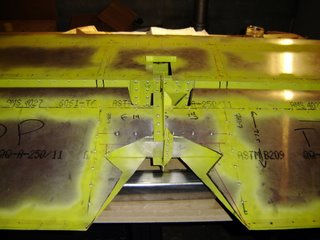
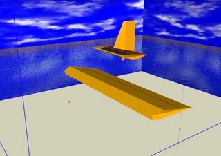
This picture illustrates that I placed the horizontal stabilizer mounts 10mm to far inside on both sides.

Two options exist in my mind for fixing this.

The first option is to create a custom mount from the fuselage side shaped to clear the flange of the stabilizer's mount. This would require a spacer and a much longer bolt. It also increases the chance of the mount cracking.

The second option is to open the stabilizer and move the mounts 10mm outside. This may require some work to the spar.

The controls are coming along nicely. The push rods and flaperon bellcranks are all connected. The flaperon mixer is also connected. The pushrods terminate where they will exit the fuselage.

I also figured out the wiring for the strobes and nav lights. They were pretty easy to deal with, but finding a suitable location for the control unit may be tricky.

Wednesday, August 16, 2006

I trimmed about 10mm from the gusset. Now the full range of motion on the elevator is defined by the horns hitting each other, so about 45 degrees each way.

Last night my neighborhood had a block party. This was a belated event from the "Neighborhood Night Out" that happened on the 1rst.

My place is on a small block in the NE corner of Ballard. It's fairly quite with many long time residents. Well as the new people, we were asked which house was ours. My response was normally something like "The house with all the strange construction noises". Based on the AOPA, EAA, SPA, and BFI stickers many had already figured out that I was a pilot, but hadn't realized what the noise was.

I got the normal questions and responses like: "Like a remote controlled plane?", "That's legal?", "How will you fit it in your garage?", and so on. In the end about 15 neighbors ( at once ) ended up in my garage to see the project. I tried to answers everyone's questions about the tools, materials and inspection process.

In the end a number of people expressed interest in flying and in experimental aviation. Hopefully more people will pop their heads into the garage.

It was a good experience, especially since I missed the Eastside EAA meeting.

Monday, August 14, 2006


I heard back from Zenith builder support today. For some reason my hinge hole is closer to the gusset bracket than it should be. I measured exactly 135mm from the center hinge bracket flange end, but I didn't verify the measurments of the gusset. According to Caleb the factory demo plane has 11mm from 7H5-3 to the edge of 7H5-4. So I'll trim about 10mm from the gusset and perhaps add a doubler to the gusset. Also according to Caleb, trimming the gusset is not an abnormal step to take to allow full motion.

It also turns out that you need to drill the holes for the cotter pins on the outboard hinge pins. I'll have to drill out the rivets ( getting those out of the elevator will be a pain! ) and then conscript a drill press to make a 1/16th" hole.

Saturday, August 12, 2006


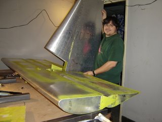
The empennage is riveted. A few small questions still remain. First the hinge pins do not seem to have holes for the cotter pins. The second question is about which side the center hinge bracket goes in relation to 7H5-3 ( horn angle ). If the bracket is on the outside then the upward elevator motion is interrupted by 7H5-4 ( center hinge gusset ). If the bracket is moved to the inside then the elevator is slightly out of position and more of the center elevator hinge will have to be removed to achieve full movement.

In total I spent about six hours working on the plane and another hour playing with Sketchup and the paint job.

Of course this photo was taken at the end of the six hours... and at about 11pm.

Next up flaperons!


Project Status:
Paint Design: 2 hour spent ( 1h, 1h )
Elevator DONE!: ~31.5 hours spent ( 3h, 1.5h, 3h, .5h, 3.5h, 2h, 4h, 1.5h, 2h, 4.5h, 1h, 6h )
Horizontal Stabilizer DONE!: ~28 hours spent, 3 pieces replaced ( 3h, 2h, 2h, 2h, .5h, 1.5h, 3.5h, 1.5h, 5, 4.5, 2h, .5h )
Rudder DONE!, minus horn : ~16 hours spent, ( ~8h, ~8h )
-----------------------
Total Done: ~78.5 hours

Friday, August 11, 2006

I took delivery of the flaperon / slats kit on Wednesday. The crate is still closed and an inventory has not been taken. While waiting for the crate I worked on the hinges for about an hour and cleaned up the garage to make room for the new crate.

When I skinned the elevator I went ahead and drilled the elevator channels not realizing that the horn brackets would go there. When it came time to put the horn brackets on I needed to drill out a few rivets and fit the brackets through the existing holes. That worked for the bottom, but for all four brackets to join nicely I had to drill new holes into the spar. One of the holes was a little close to the new hole, so I fashioned a "patch" that goes over the the previous holes and restores any strength that may have been lost without affecting the fit of the horn brackets.

Initially I thought I borked the newly received center hinge by drilling the hinge hole too early. I had measured the 135mm from the bracket flange tip up the centerline. When I did a quick test fit against the bracket it attaches too I freaked out when the hinge hit against the elevator spar and was at least 1/4" away from the desired hole.. After calming down a little I realized what needed to be done was the following procedure: I clecoed the center hinge to the bracket on the outside of the flange and rotated the brackets. While rotating I used a Sharpie to determine the area that needed to be ground away. After fifteen minutes of using the rasp I had the correct fit.

The next step is to deal with the outside hinges and make sure everything is co-linear. Yeah.

I hope to have a completed tail section on Saturday with the flaperons starting on Sunday.

Google Sketchup is a cool tool I've used in the past. When we moved I spent a few hours with it and made a mockup of our new dwelling along with the major furniture with real measurements. This worked better than the old graph paper alternative because the digital objects gave a better sense of volume. I'm taking the same approach to designing my paint scheme. I spent about an hour making a digital elevator and horizontal stabilizer. The next step is to create a texture to be applied over the base "paint". The paint scheme I have in my head is fairly grand. Spending at least 400 hours on construction and then not taking that extra step to make my plane stand out is inconceivable to me. I want to make sure that the paint job looks good from several conceivable angles and translates well.


Project Status:
Paint Design: 1 hour spent ( 1h )
Elevator: ~25.5 hours spent ( 3h, 1.5h, 3h, .5h, 3.5h, 2h, 4h, 1.5h, 2h, 4.5h, 1h )
Horizontal Stabilizer: ~28 hours spent, 3 pieces replaced ( 3h, 2h, 2h, 2h, .5h, 1.5h, 3.5h, 1.5h, 5, 4.5, 2h, .5h )
Rudder Done, minus horn : ~16 hours spent, ( ~8h, ~8h )
-----------------------
Total Done: ~71.5 hours

Saturday, July 29, 2006


Has anyone had the following problem?

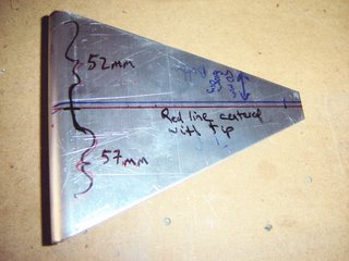
I'm starting my elevator/stab hinges and noticed a difference between the builder's manual, the plans and the manufactured piece supplied by Zenith concerning the Center Hinge Bracket ( 7H3-3SP ).

Using the plans I measured 50mm into the flange to make a mark to draw the perpendicular line. This line was off center with the bracket tip by about 2mm. The builders manual states that the line should be centered with the tip.

When tried to figure out why this was and I realized that the flange was 109mm in length, not 107mm as stated in the plans.

Since these measurements are enclosed by boxes on the plans, I assume they are critical, especially since being off will cause problems with the elevator's movement.

Is it better to use the tip center to determine the line knowing that one side of the piece was manufactured 2mm to long, possibly grinding down that side? ( my guess )

Or would it be better to use the line drawn 50mm in? ( seems like that would weaken the hinge )

Update 1: I think that the piece was cut wrong AND that the flange was bent in the wrong direction.

Update 2: Zenith is sending me a new piece. Thanks to Caleb and Nick for their support.

Project Status:
Elevator: ~20 hours spent ( 3h, 1.5h, 3h, .5h, 3.5h, 2h, 4h, 1.5h, 2h )
Horizontal Stabilizer: ~28 hours spent, 3 pieces replaced ( 3h, 2h, 2h, 2h, .5h, 1.5h, 3.5h, 1.5h, 5, 4.5, 2h, .5h )
Rudder Done, minus horn : ~16 hours spent, ( ~8h, ~8h )
-----------------------
Total Done: ~65 hours

Tuesday, July 11, 2006


We started on the elevator tonight after cutting the top stabilizer and re-clecoing it back down. About 30 minuts was spent on the stabilizer and about 3 hours on the elevator.

The elevator spar was drilled for the 7H1-7s and the side brackets were cut out. Finding the position of the ribs was an easy job made hard by the wording of the directions.

The side brackets still need to be drilled. According to the manual a tolerance is 1mm, so additional measuring and double checking needs to be done.

Project Status:
Elevator: ~3 hours spent ( 3h )
Horizontal Stabilizer: ~28 hours spent, 3 pieces borked ( 3h, 2h, 2h, 2h, .5h, 1.5h, 3.5h, 1.5h, 5, 4.5, 2h, .5h )
Rudder Done, minus horn : ~16 hours spent, ( ~8h, ~8h )
Workshop Done: ~8 hours

Friday, July 07, 2006

Q: "Why don't you go to bed like a normal human being?"
A: "Because I am de-burring"

We got the top of the horizontal stabilizer skin drilled and deburred tonight. Corrosion protection and the cut for the control lines will finish that up.

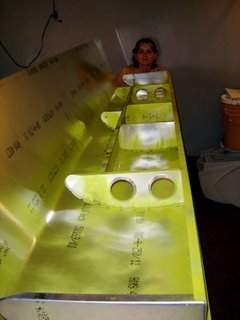
Getting the skin tight over the stabilizer was a major pain. Using the rachet straps worked, BUT it was an impossible operation by myself. The piece of wood that was used to protect the overhang would slip and needed to be duct taped into position. The tightening of the straps would cause the stabilizer to move forward. The skin had to be tugged on to get it flush with the front of the spars.

Drilling the skin was also problematic. I had a slight splay out for the two full ribs that attach to both the front and rear spar. While I could measure and feel where the spars were, I still needed to drill some "pilot" holes to double check my measurements, release the skin, adjust the rivet lines, re-tighten and repeat.

Currently I am confused about when the whole thing gets riveted.

Reading through the rest of the tail section I found that the stabilizer doesn't get riveted until after the elevator is done. That is a bit of a buzz kill since I really want to consider the horizontal stabilizer "done" even though I know some more mounting bracketry needs to be placed on it for the mating of the elevator.

Saturday will be spent at the big Arlington fly-in and Sunday will be spent starting the elevator.

Project Status:
Horizontal Stabilizer: 27.5 hours spent, 3 pieces borked ( 3h, 2h, 2h, 2h, .5h, 1.5h, 3.5h, 1.5h, 5, 4.5, 2h )
Rudder Done, minus horn : ~16 hours spent, ( ~8h, ~8h )
Workshop Done: ~8 hours

Tuesday, July 04, 2006

We got the bottom stabilizer skin corrected and riveted today. We used several clamps to make sure the piece was flat and without any twist.

Four and half hours were spent on the correction, de-burring and corrosion protection along with cutting the holes in the skin for the two mounting brackets.


Project Status:
Horizontal Stabilizer: 25.5 hours spent, 3 pieces borked ( 3h, 2h, 2h, 2h, .5h, 1.5h, 3.5h, 1.5h, 5, 4.5 )
Rudder Done, minus horn : ~16 hours spent, ( ~8h, ~8h )
Workshop Done: ~8 hours
The garage was filled with people on Monday. First a coworker came by and lended a hand and observed. A large amount of work got done, most importantly the drilling of the bottom stabilizer skin.

Mark Townsend from Can-Zan came by on his way to Arlington http://www.can-zacaviation.com and gave me some great advise and looked over the stabilizer and gave me some good corrections.

More tools are needed for the corrections, but I should be able to finish the stabilizer this weekend.

Thursday, June 29, 2006

The first milestone of the garage was reached. After 1.5 hours of work the brackets were drilled into the correct position, cut as required and deburred. The existing skeleton was checked for burrs and then riveted. The skin was measured and positioned. The next task will be to skin the stab and then move on to the elevator.


Project Status:
Horizontal Stabilizer: 16 hours spent, 3 pieces borked ( 3h, 2h, 2h, 2h, .5h, 1.5h, 3.5h, 1.5h )
Rudder Done, minus horn : ~16 hours spent, ( ~8h, ~8h )
Workshop Done: ~8 hours